If your car did not include the Emergency Flasher option when built, then this can be added by using the following kit I purchased from Jeff Carter (jcauto.com). The Emergency Flasher was an option for cars beginning in 1960. I could not find a reference for prior years, but this same kit could be built if you can find the necessary parts and build it yourself (or maybe it already exists).
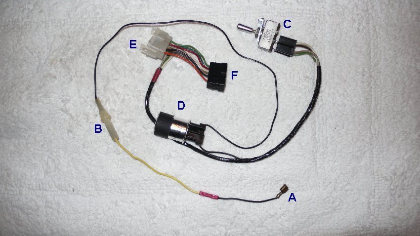
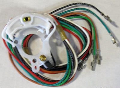
Here is the new wiring harness that I bought from Jeff. This allows for a new 12 volt source that feeds the blinker can then feeds a switch that runs to the plug junction in the wiring harness exiting the turn signal switch in the steering wheel.
A. - The new power source.
B. - Inline fuse (optional)
C. - Switch (input black wire, output tan, light green and white).
D. Blinker Can.
E/F - The new plug jumper harness (7 wire as in the original)
The first step was to disconnect the wiring harness plugs that runs down the steering wheel post. They are easily unclipped with the help of a screwdriver. Next orient the new plug in the kit and line up the correct wire color orientation, and attach the two plugs inline with the originals. The only other connection would be the power source. I had recently worked on the accessories above the radio and the glove box was out of the car. I ran the jumper wire over the radio and used the plug above the Map Light for the 12 volt source. The original wire for the light had a modular plug with a plastic cover. To use this plug for both wires I had to make a short jumper so that the harness wire attached to the light and the light wire attached to the double female socket on the new kit. Now all I had to do was tuck everything under the dash and secure with a Zip tie out of sight. Total time for this was less than 1 hour. The new flashers worked as advertised and with the original 15 amp fuse in the fuse block and secondary fuse in the power line also 15 amp I feel confident that it is well protected.
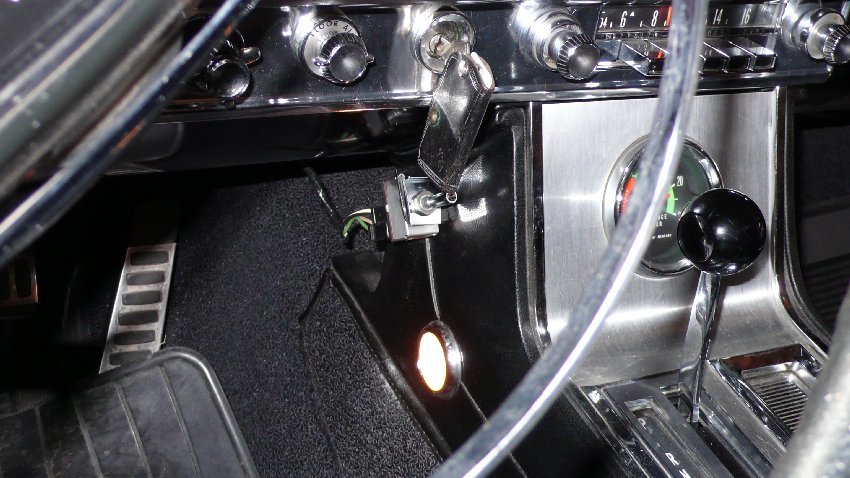
The actual installation of the switch in the console side panel was chosen to minimize any damage to the actual dash. I made an aluminum angle bracket that was screwed to the side panel and a hole for the switch itself. Once installed it allows for easy access to the switch without getting in the way of normal dash switches.
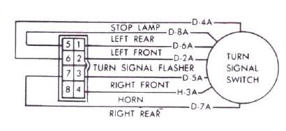
This is the wiring diagram found in the Service Manual for 1964 Chrysler. The number blocks are identical to the color version below.
Here is the only picture of the Turn Signal Switch that I could find. The colors seem to match the diagram also below.
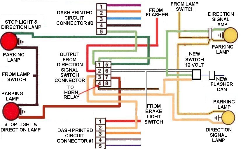
This is the diagram that shows how the flasher kit works. The turn signal switch assembly separates the front lamps wiring (light green and tan) and the back lamps wiring (dark green and dark brown) find their way to the right and left sides of the car separately when the turn signal is activated. The brake light switch wire (white) would feed a continuous signal to the rear lamps when the pedal is pressed and the feed is activated and this allows for a continuous high beam in the rear only (the front does not stay steady when the brake light is pushed). By placing the harness jumper (7 wire) inline with the existing harness all you are adding is an additional source of intermittent signal with the new flasher. This also feeds the blinker lights in the dash (thru light green and tan wires on the printed circuit connector) and front lamps (thru light green and tan wires also) and at the same time and the rear lamps thru the flasher switch (dark green and dark brown wires). The switch has one black wire coming in from a continuous power source. The three wires out are only hot when the switch is activated (light green, tan and white).
Remember, the front/rear directional lights are active only when the key switch is activated, and will not work when the switch is off. The Emergency Flasher lights front/rear are on continually, and will work regardless of the key switch position. If the right or left turn signal is used when the key switch is on and the Emergency Flashers are active the resultant light display will be a sporadic flashing activation depending on which is sending power at that instant in time.